One Polishing Arrangement for Tank Shells and Dished Ends
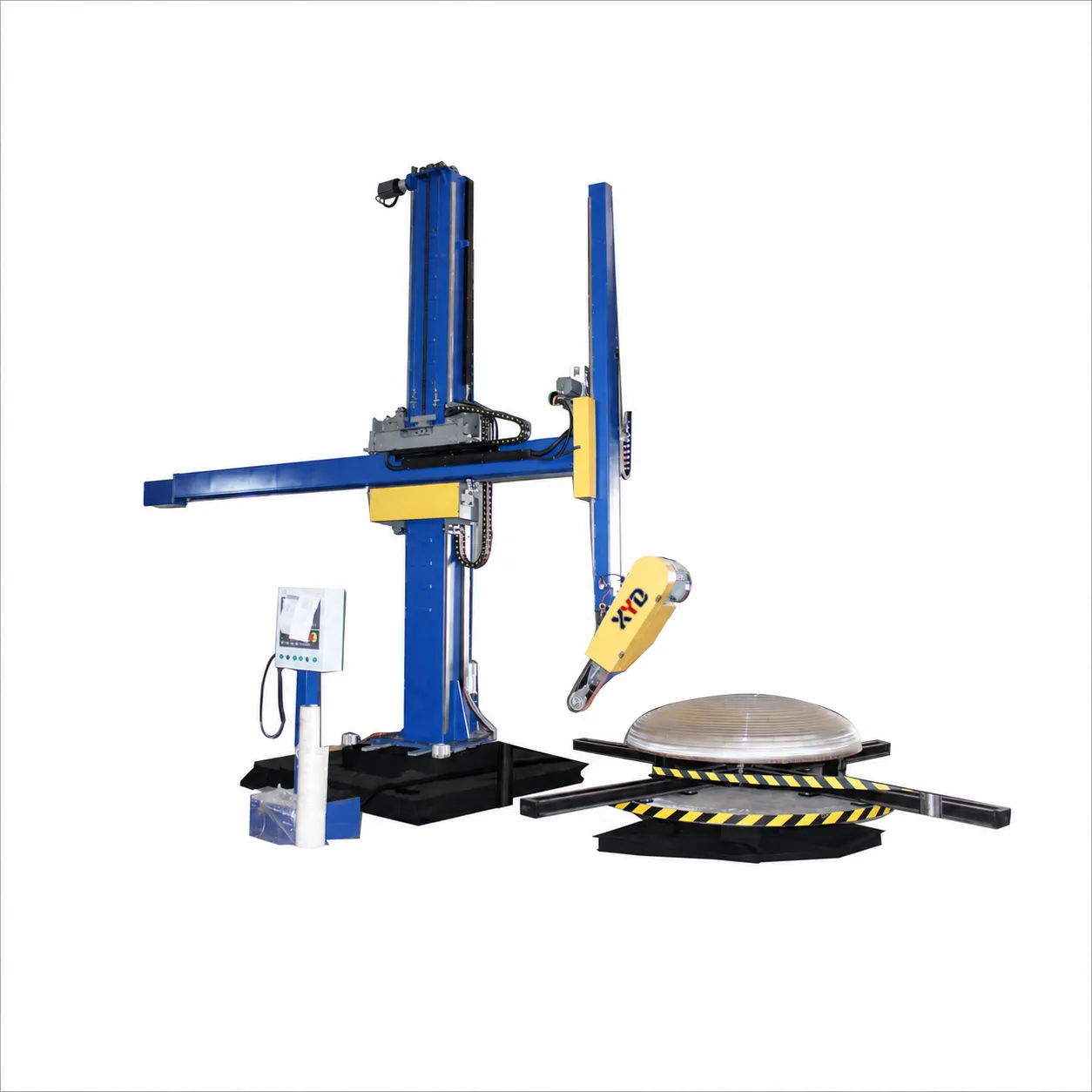
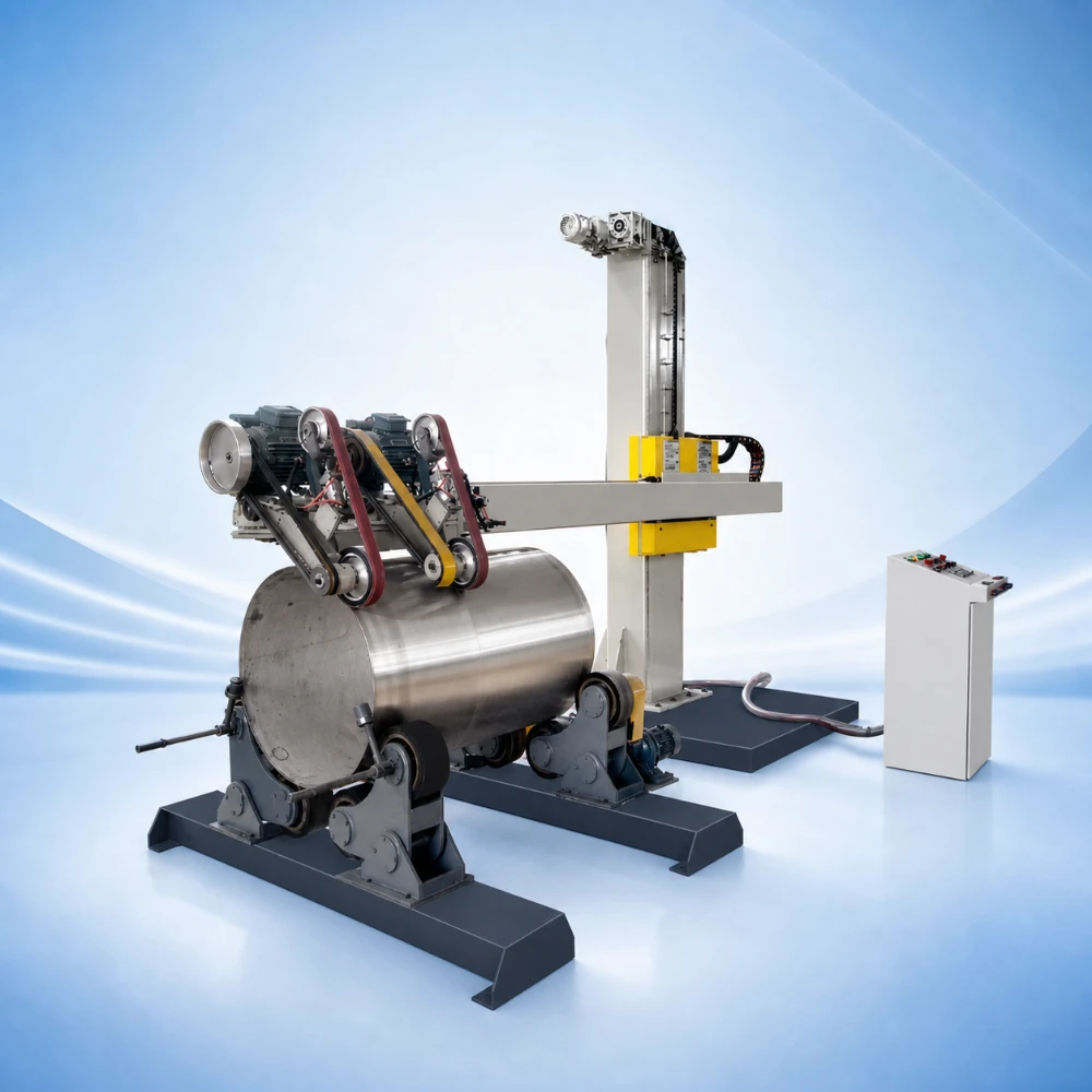
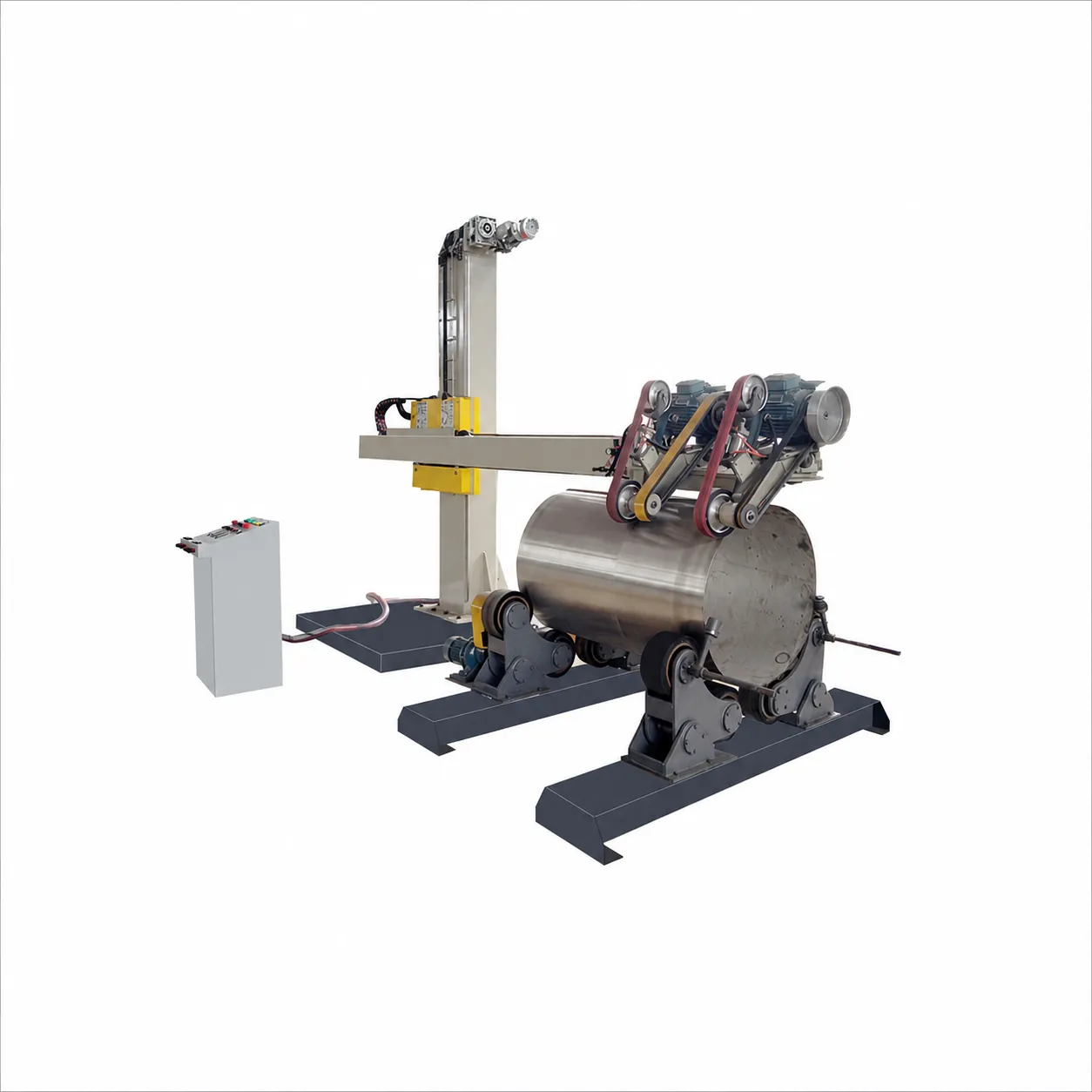
For vessel workshops producing both cylindrical shells and dished ends, the BY-JY Tank & Dished End Polishing Machine combines tank exterior polishing with dished-head interior finishing. It is a practical equipment category for food and beverage vessel fabricators, process-equipment manufacturers and pressure-vessel workshops that need an agreed finish on these two different component shapes.
Start with the surfaces your production team actually needs to finish. The current range is 500-3,000 mm for dished heads and 800-3,000 mm for tanks, with processing depth up to 1,000 mm. Diameter alone does not establish access to a deep head, tight transition radius or a component with fittings.
Two Workpiece Types, Different Support Requirements
- Cylindrical shells: roller supports locate and rotate the tank while the polishing head works along the selected exterior surface. Check shell length, balance and roller contact positions.
- Dished ends: the head turntable and polishing path must suit the crown, knuckle and depth of the head. An interior contour needs a different access review from a tank exterior.
- Mixed production: review the fixture change, lifting method and recipe change between shells and heads. The combined arrangement is not a claim that both parts run simultaneously.
Set the Path, Then Select the Abrasive Sequence
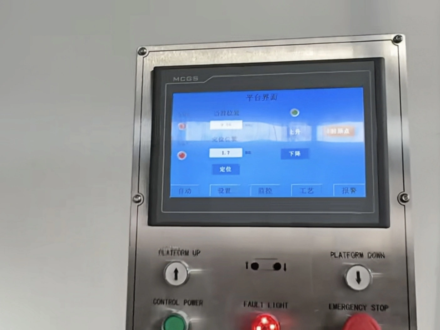
The listed servo and frequency-inverter drive arrangement uses a PLC with a 10-inch touchscreen. Stored parameter recipes support repeat work, and configurable paths allow up to five points with adjustable interpolation speed. Five path points describe the recipe, not five independently controlled axes.
For surface preparation and final buffing, the quick-change tooling includes a 2,000 x 50 mm belt, a 250 x 50 mm flap wheel, sisal wheels and cloth wheels. Select the sequence for the material, existing marks and agreed appearance; changing the tool does not remove the need to approve the recipe on a representative component.
Current Product Specifications
| Parameter | Current product specification |
| Model | BY-JY |
| Dished-head diameter | 500-3,000 mm |
| Tank diameter | 800-3,000 mm |
| Processing depth | Up to 1,000 mm |
| Maximum load | Standard: 1 ton; optional configurations: up to 20 tons |
| Controls | PLC with 10-inch touchscreen; controller brand to be confirmed |
| Drive | Servo motor and frequency inverter; component brand to be confirmed |
| Grinding path | Up to five points with adjustable interpolation speed |
| Operation | Automatic curved-surface polishing |
| Tooling | 2,000 x 50 mm belt; 250 x 50 mm flap wheel; sisal and cloth wheels |
| Listed production efficiency | Up to 8 m2/h under mirror-finish conditions; application-dependent |
| Original positioning entry | 0.1 mm/s, described as positioning accuracy in the source page. The unit and intended specification require confirmation. |
The standard support load is 1 ton. Configurations up to 20 tons are optional and require the corresponding workpiece support and handling arrangement. Listed output up to 8 m2/h under mirror-finish conditions depends on the incoming surface, geometry and abrasive stages. The original positioning entry of 0.1 mm/s has an unresolved unit and must not be treated as confirmed positional accuracy.
Confirm Changeover and Workshop Space
An automatic loading and unloading arm is listed as an optional module with an additional 2.5 m space requirement. Confirm its working envelope together with the roller table, turntable, lifting access, operator position and maintenance clearance; the extra dimension is not a complete installation footprint.
- Tank drawing: diameter, length, weight and exterior surfaces to finish.
- Dished-end drawing: profile, diameter, depth, weight, openings and interior finishing area.
- Material, wall thickness, initial surface, allowable removal and a finish reference.
- Support configuration, loading equipment, changeover frequency and required complete-cycle output.
Agree roughness or appearance acceptance for the actual component. Polishing-machine capability does not establish hygienic or pressure-vessel compliance. For predominantly cylindrical-shell work, compare the Tank Polishing Machine; for larger programmable vessel finishing, review the CNC Polishing Machine.