Tank Surface Finishing for Vessel Fabricators
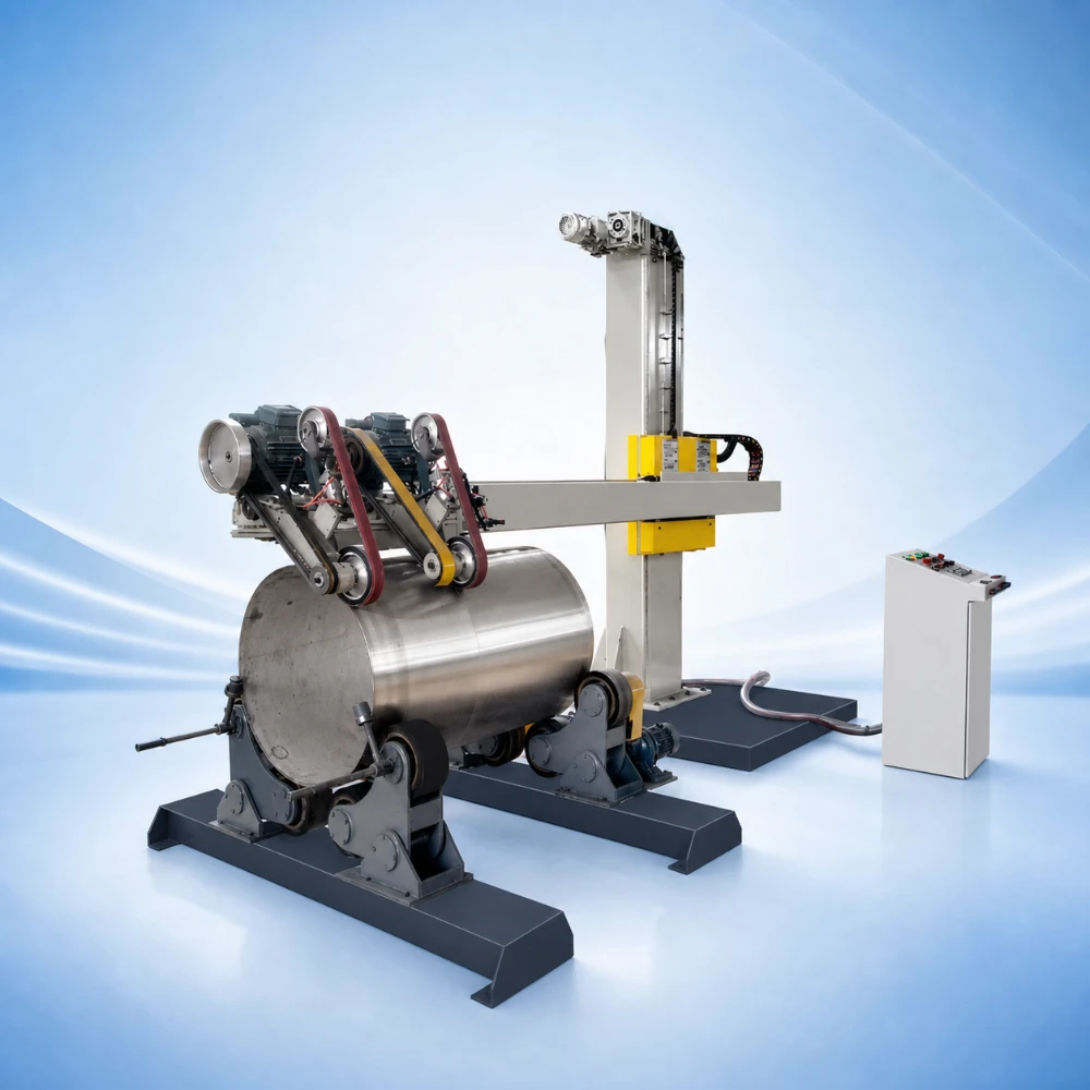
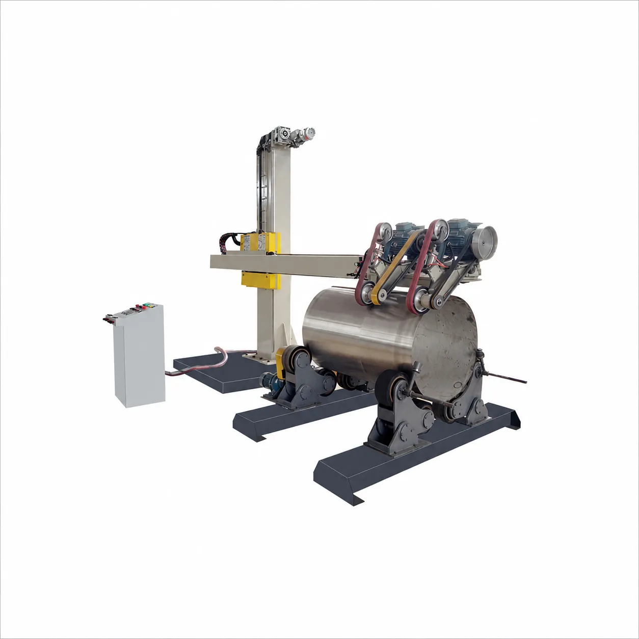
This Tank Polishing Machine is for workshops producing medium and large cylindrical vessels: storage and reaction tanks, stainless-steel process equipment and other tank components with defined surface-finish requirements. Its listed dual-head configuration combines roller-supported workpiece rotation with PLC recipe control for the selected internal or external surface.
The diameter range is 500-5,000 mm, with extension to 6,000 mm optional. Before choosing a configuration, identify whether the job is broad shell finishing, local weld blending or an internal surface reached through an opening. These tasks can require different tools and working positions even on tanks of the same diameter.
Check Shell Access Before Comparing Capacity
- Exterior shell: review the full tank length, support spacing, roundness and areas interrupted by nozzles or brackets.
- Interior surface: show the entry opening, distance to the finishing area and internal fittings. A listed diameter range is not a guarantee of internal access.
- Workpiece support: specify weight, balance and the roller contact zones. A support adequate for one empty shell may not suit a differently assembled vessel.
Coordinate Rotation, Head Travel and Abrasives
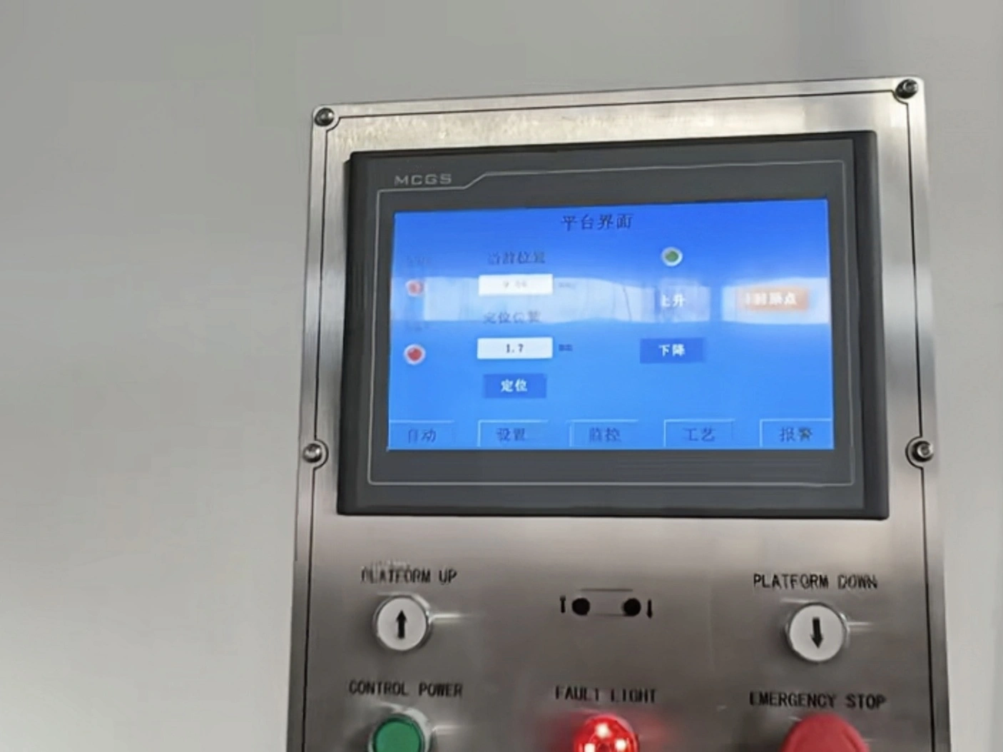
The listed system links beam feed and roller rotation through dual-inverter control. PLC/HMI recipes organize the polishing stages; the current configuration description also includes constant-pressure operation, PID speed control and overload protection. Reusing a recipe requires the same validated workpiece support, tooling and incoming condition.
The spindle motor is rated at 5.5 kW with stated torque of 35 N-m. The modular quick-change abrasive system allows the preparation and finishing stages to be arranged around permitted removal and final texture. Raised weld material and the final shell appearance should be reviewed as separate stages, not treated as a single universal polishing pass.
Current Product Specifications
| Parameter | Listed specification |
| Workpiece diameter | 500-5,000 mm; expandable to 6,000 mm |
| Power | 8 kW total; 5.5 kW spindle motor |
| Rated motor torque | 35 N-m |
| Control system | PLC and dual-axis inverter synchronous drive |
| Speed range | 1-20 rpm, stepless adjustment |
| Abrasive system | Modular quick-change system |
| Listed surface roughness | Ra ≤0.4 µm |
| Listed efficiency | 8 m2/hour for continuous mirror finishing |
| Roller load | Standard 2 tons; upgradable to 20 tons |
| Listed synchronization error | Less than 0.5% |
The standard roller load is 2 tons; upgrading to 20 tons is optional. Likewise, the 6,000 mm diameter extension is not part of the standard 500-5,000 mm range. No fixed tank length is specified in this table, so head reach and support layout must be reviewed against the complete vessel drawing.
Approve the Finish and the Complete Production Cycle
The listed Ra ≤0.4 µm, 8 m2/hour continuous mirror-finishing output and synchronization error below 0.5% are current page values. Roughness, output and drive synchronization are different measurements: a synchronization figure is not proof of a particular surface finish. Agree the applicable measurement conditions for the supplied configuration.
- Provide representative material and the actual starting surface, including welds or previous grinding marks.
- Approve the abrasive stages and examine the defined surfaces after cleaning.
- Record the finish measurement or appearance comparison and any dimensional change.
- Time loading, support adjustment, polishing, consumable changes, cleaning and inspection before calculating production output.
Options and Installation Scope
Automatic tool changing, dust collection and heavier roller supports are listed as optional choices. Confirm the delivered scope, electrical and extraction requirements, lifting route, roller spacing, operator access and maintenance space in the installation drawing.
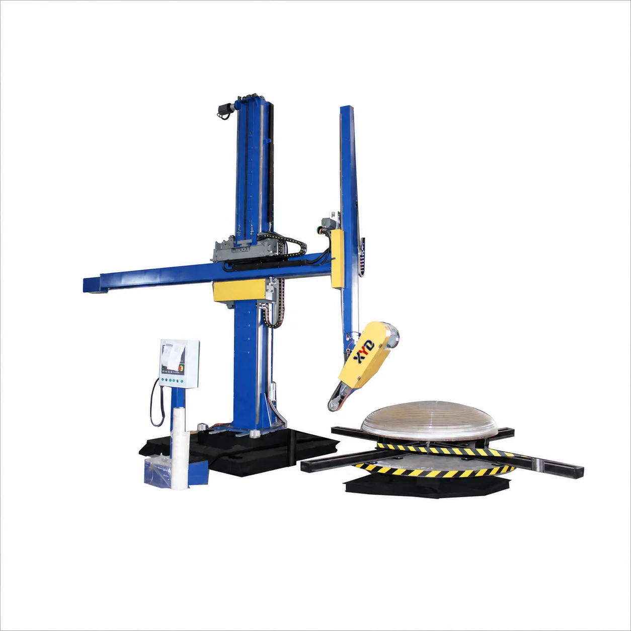
For combined shell and dished-head production, compare the Tank & Dished End Polishing Machine. For a job concentrated on a circular weld rather than the whole shell, review the Circumferential Weld Seam Polishing Machine.