Automatic Straight-Seam Welding for Repeated Sheet-Metal Parts
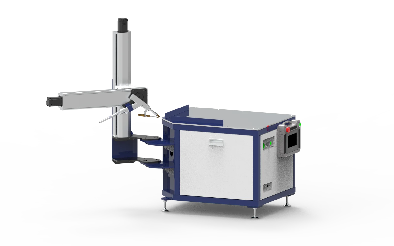
The Horizontal Automatic Welding Platform gives cabinet, enclosure and sheet-metal manufacturers controlled torch travel along straight external-corner joints. Its servo-driven motion and PLC control suit recurring parts where the weld path can be defined and the joint held in a consistent position.
Choose this arrangement when your production problem is repeatable straight travel, rather than access to curved or complex three-dimensional seams. The platform guides the welding head; the welding source, joint preparation and fixture determine whether the actual part can be welded to the required standard.
Where It Fits in Production
- Electrical cabinets and equipment housings: repeated straight outer-corner seams on formed sheet-metal assemblies.
- Battery cases and metal boxes: accessible joints with controlled fit-up and a fixture that supports the complete seam.
- Kitchen, food and medical-equipment fabricators: recurring enclosure components with defined appearance and inspection requirements.
Platform Layout and Joint Access
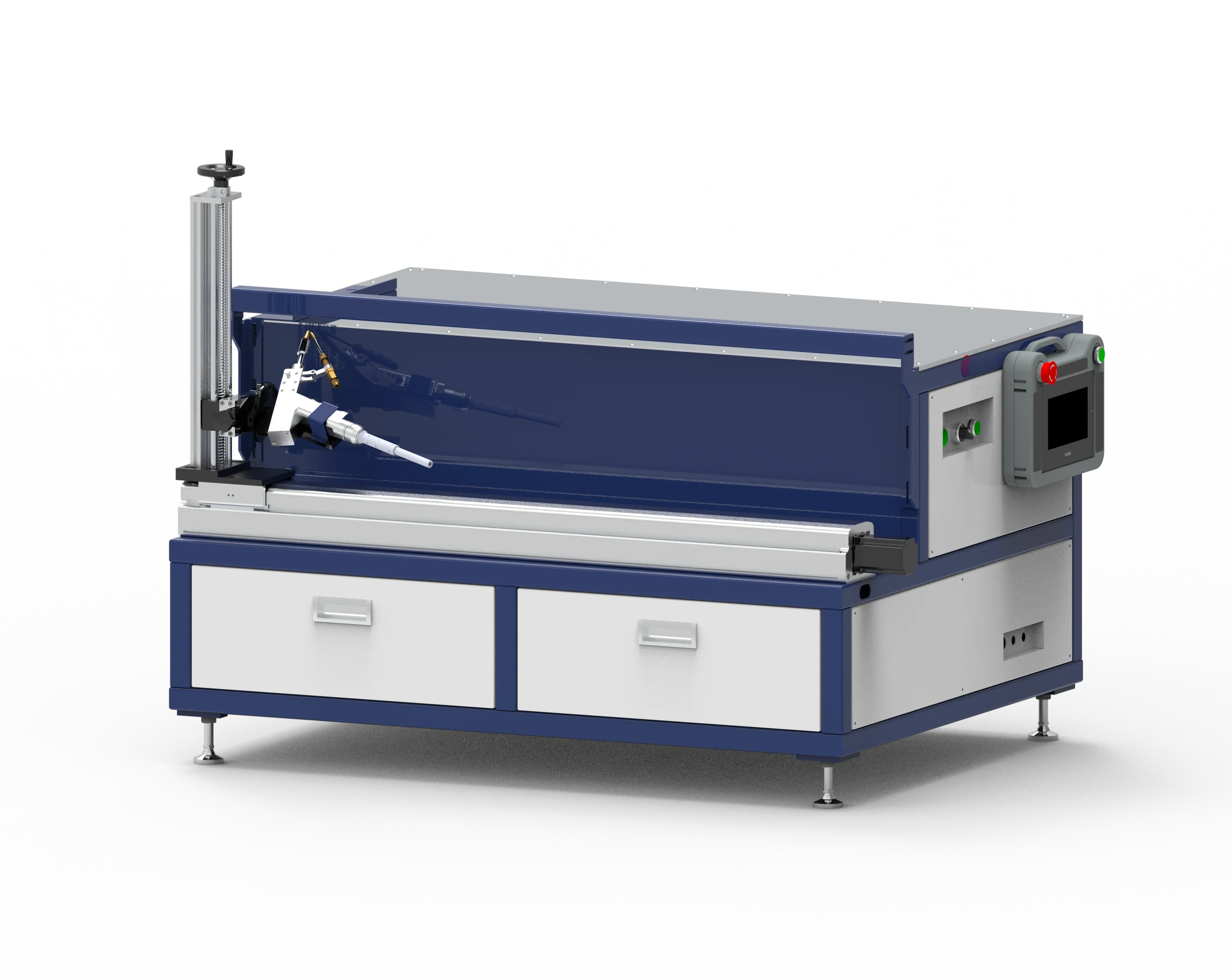
The linear guide and adjustable head support establish the travel arrangement. Check clearance for flanges, clamps, the torch, cables and wire feed along the complete path. Overall machine dimensions are not the maximum workpiece envelope or a guarantee that every seam on a part is reachable.
Select the Weld Sequence
- Continuous welding: an uninterrupted programmed path between the chosen start and end points.
- Spot, stitch and multi-segment modes: selected weld locations or sections where the drawing calls for gaps.
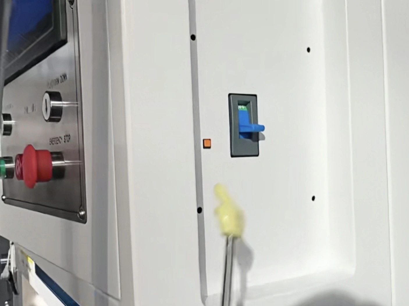
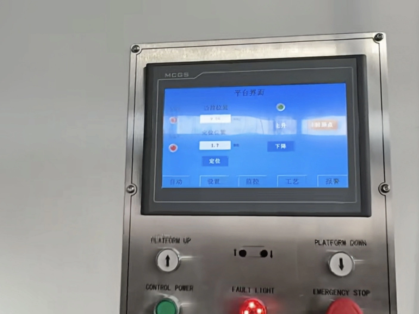
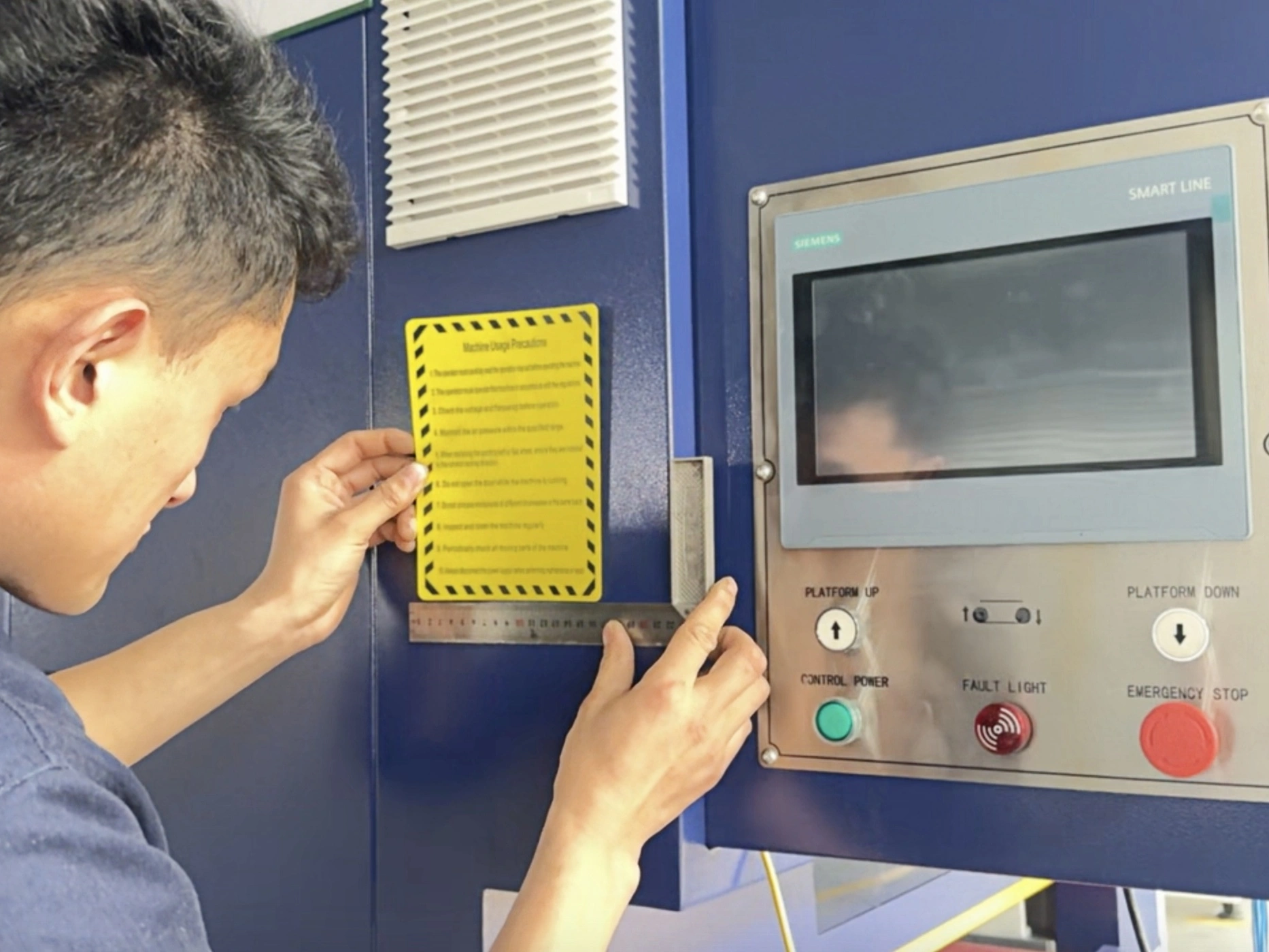
- Manual/automatic operation: setup and production modes, with touchscreen settings and foot-operated cycle start.
A repeatable cycle starts with repeatable loading and clamping. Assess locating, welding, unloading and inspection together; automatic travel alone does not establish output per hour.
Source Integration and Material Range
Handheld laser, TIG and gas-shielded welding equipment can be considered for integration. Confirm the head mount, control signals, shielding-gas or wire-feed arrangement, cooling and protective measures with the selected source. Process compatibility does not mean every welder connects without interface work.
The published applications include stainless steel, carbon steel and aluminum alloy, with a listed plate-thickness range of 0.4-6 mm. The suitable range for a particular joint depends on source power, material, fit-up and process settings. Confirm penetration and appearance on representative parts.
Published Model Comparison
| Parameter | BR-HJPT-1000mm | BR-HJTP-1600mm | BR-HJPT-2000mm |
|---|---|---|---|
| Y-axis effective travel | 1,000 mm | 1,600 mm | 2,000 (unit to confirm) |
| Travel drive | Servo | Servo | Servo |
| Control system | PLC | PLC | PLC |
| Equipment dimensions (listed values) | 1250 × 940 × 640 | 1850 × 990 × 640 | 2250 × 990 × 640 |
| Weight | 165 kg | 220 kg | 350 kg |
| Power supply | Single-phase AC 220 V ±10%, 50 Hz | Single-phase AC 220 V ±10%, 50 Hz | Single-phase AC 220 V ±10%, 50 Hz |
Before selecting capacity: preserve the distinction between travel and usable welding length. Fixture clearance and the approved start/end positions affect the seam that can actually be welded. The 2000-model entry was originally printed as "2000m"; its travel unit and the omitted dimension units require confirmation in the machine-specific technical agreement. Model labels above retain the product-page spelling.
Define the Supplied Workstation
- Part: a dimensioned drawing showing material, thickness, joint fit-up, seam length and loading orientation.
- Equipment: the existing welding-source model, torch dimensions, control interface and cooling needs.
- Scope: platform, source, fixtures, wire feeder, shielding-gas equipment and protective enclosure as separately agreed items.
- Acceptance: weld pattern, penetration, visible bead requirements and inspection method on an approved sample.
For upright outer-corner joints with a different loading arrangement, compare the Vertical Corner Welding Platform. For application and weld-sample references, see the Horizontal Straight Seam Welding Platform.
English Product Overview
This two-page overview from ANHUI BONRAY CO., LTD covers horizontal straight-seam welding applications, workholding photographs, weld samples and source integration. It is an application reference, not an operating manual. Use the technical specifications above for the listed model comparison.