Vertical Outer-Corner Welding for Sheet-Metal Enclosures
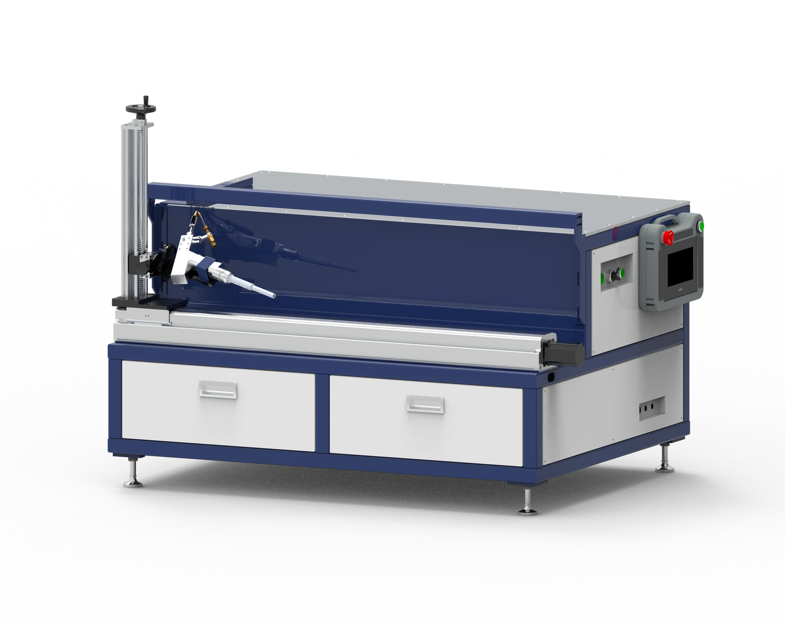
The Vertical Corner Welding Platform supports programmed welding-head movement for outer corners on cabinets, enclosures and fabricated equipment components. It suits repeated part families that can be located in a fixture with the seam accessible beside the upright head-support arrangement.
Cabinet builders, kitchen-equipment fabricators and sheet-metal job shops should evaluate this configuration around corner geometry and loading orientation. The platform controls positioning and travel; the connected source, joint preparation and fit-up determine penetration and final weld appearance.
Check the Corner and Loading Arrangement
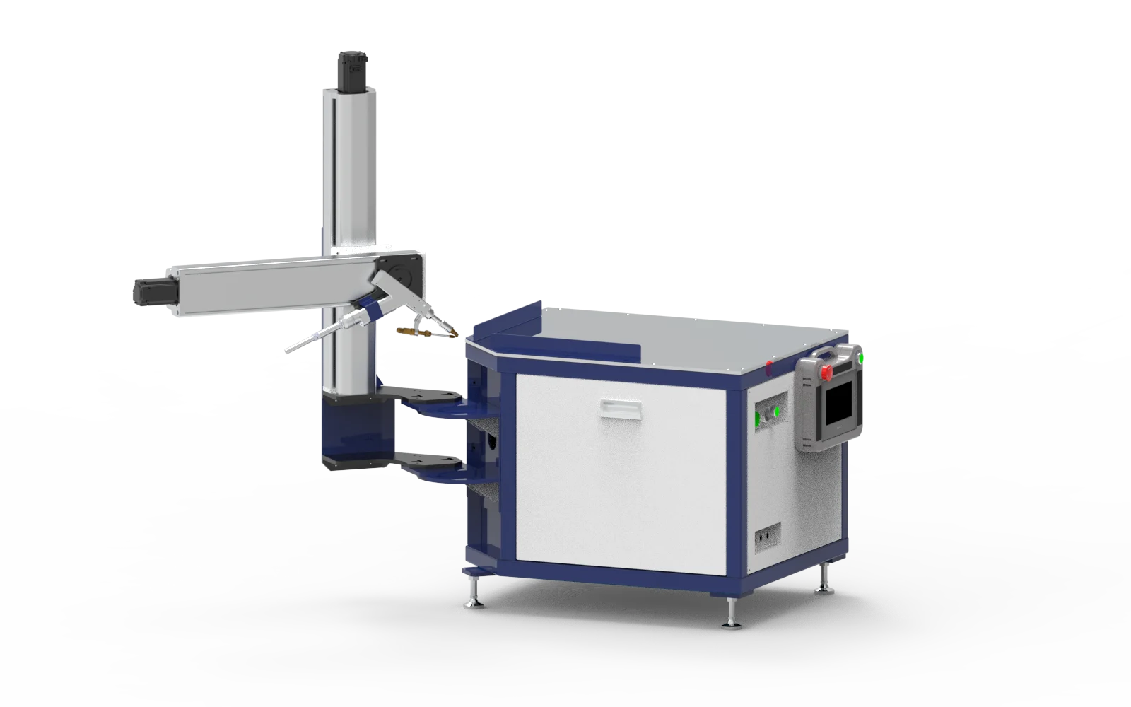
- Seam access: show the corner, bends, flanges and adjoining panels on a part drawing.
- Workholding: locate and support the part while keeping clamps clear of the programmed head path.
- Connections: allow room for torch cables, wire feed and cooling connections without interference.
The overall footprint is not a maximum part envelope or an effective weld length. Confirm the permitted movement and fixture arrangement for the supplied configuration, including clearance before and after each segment.
Control the Sequence Around the Joint
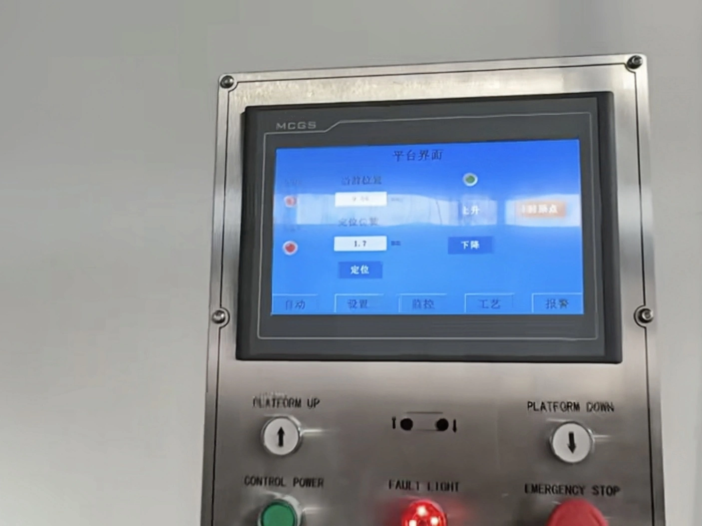
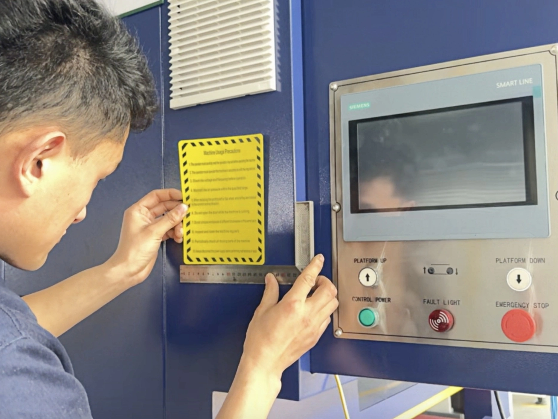
The equipment documentation describes PLC programming, manual and automatic modes and adjustable start/end positions. Multi-segment sequences and self-fusion or filler-wire processes can be considered with the integrated equipment. Use the approved machine instructions for programming and operation.
Production planning should include locating, clamping, welding, unloading and inspection. A repeatable head path does not by itself establish a guaranteed production rate or compensate for variable joint gaps.
Select the Welding Source
- Laser: review head mounting, control signals, cooling and laser-specific guarding/interlocks.
- TIG: confirm torch dimensions, mount, cooling where required and start/stop coordination.
- MIG or gas-shielded welding: check torch mounting, wire-feed clearance and source-control interface.
The listed stainless-steel application range is 0.6-6 mm, dependent on welding-source power and process. Carbon steel and aluminum alloy are also listed applications, but do not assume the same thickness capability across every alloy, joint or source.
Published Equipment Specifications
| Parameter | Specification |
|---|---|
| Main body (L x W x H) | 1,200 x 1,500 x 1,350 mm |
| Main body weight | Approximately 175 kg |
| Control cabinet (L x W x H) | 300 x 300 x 500 mm |
| Control cabinet weight | Approximately 38 kg |
| Power supply voltage | 220 V |
| Stainless-steel plate thickness | 0.6-6 mm; dependent on welding-source power and process |
Installation scope: the page separately lists the main body and control cabinet. Confirm their supplied arrangement and handling information; do not treat these entries as a verified combined shipping weight. The listed 220 V supply is for the platform, not confirmation of the welding source or cooler requirements.
Define the Complete Workstation
Agree whether the source, torch mount, fixtures, wire feeder, shielding-gas equipment, cooler and protective measures are included. Reserve space for loading and maintenance as well as the equipment footprint. Integration and commissioning should be performed by qualified personnel using the applicable manuals.
- Workpiece: drawing, material, thickness, dimensions, weight and corner/seam locations.
- Integration: existing source make/model, torch geometry and control interface.
- Production: proposed fixture, loading method, batch quantity and complete-cycle target.
- Acceptance: representative corners with agreed fit-up, penetration, bead appearance and inspection criteria.
For straight seams suited to horizontal workholding, compare the Horizontal Straight Seam Welding Platform. Select the orientation that gives the fixture and welding head access to the actual joint.