Finish Accessible Bore Surfaces Before Assembly
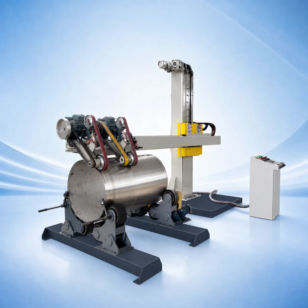
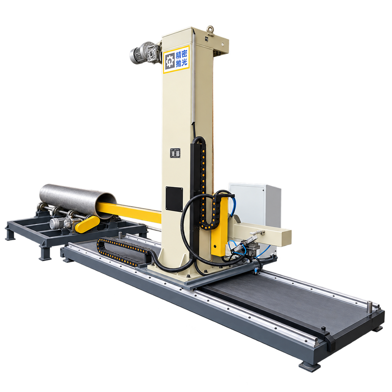
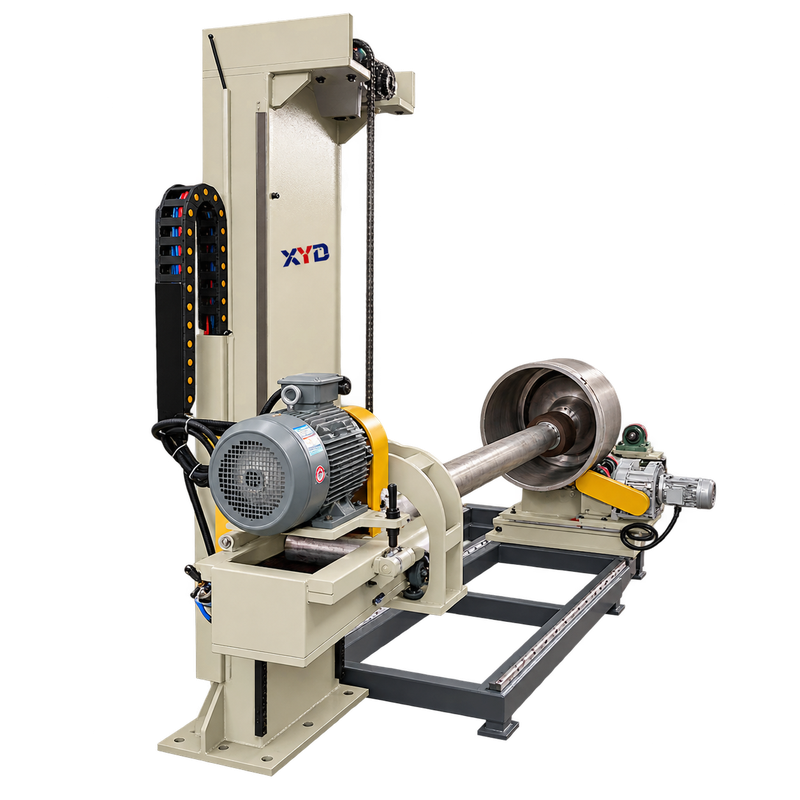
An internal tube polishing machine for manufacturers preparing accessible bore surfaces in open-ended stainless-steel cylinders and tubular sections. The adjustable roller table supports rotation while the beam-mounted polishing assembly travels along the part.
The published workpiece diameter range is 350-1,000 mm, the maximum polishing length is 3,000 mm per pass, and the adjustable roller table is rated at 1 ton. These are separate limits: a part must also provide suitable tool access and stable support.
For Cylinder and Process-Equipment Fabricators
- Tube fabrication: internal finishing of open cylindrical sections before fitting ends, internal components or other features that restrict access.
- Cylindrical equipment: finishing suitable stainless-steel shells and tubular components where the internal surface, not only the outside appearance, forms part of the acceptance requirement.
- Contract polishing: repeat batches of compatible cylindrical workpieces with an agreed tooling sequence and surface reference.
The machine is a surface-finishing tool. Use of a component in food, filtration, water-treatment or chemical equipment does not, by itself, establish hygiene, pressure-equipment or corrosion-resistance compliance.
Check the Bore, Opening and Polishing Length
Provide inside diameter, outside diameter and wall thickness. The published diameter entry does not identify ID or OD; the range must not be read as a guaranteed minimum tool clearance. An end opening may be smaller than the main bore, and internal steps, baffles or fittings may interrupt the tool path.
A section drawing should show both ends and every region requiring finishing. The 3,000 mm figure is the polishing length per pass, not proof of full-length coverage on a longer tube. Closed-end parts and restricted bores require a separate access assessment.
Supported Rotation and Controlled Tool Travel
- Roller support: six 150 mm polyurethane rollers on an adjustable 1-ton table support the cylindrical workpiece. The listed table drive is a 370 W motor with an NMRV050 reducer at 1:80.
- Polishing drive: the main motor is rated at 4 kW; replaceable flap wheels and cloth wheels allow the consumables to be selected for the incoming surface and finishing stage.
- Coordinated motion: VFD control is listed for beam travel and workpiece rotation. Travel, rotation and tooling settings must be specified together for the actual part.
These motions support a planned polishing sequence; they do not specify a particular number of CNC axes, automatic pressure compensation or an unattended production cycle.
Open-End Access and Roller-Support References
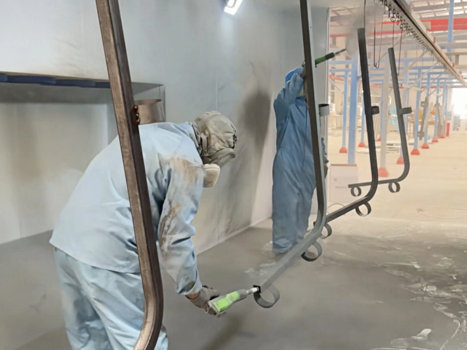
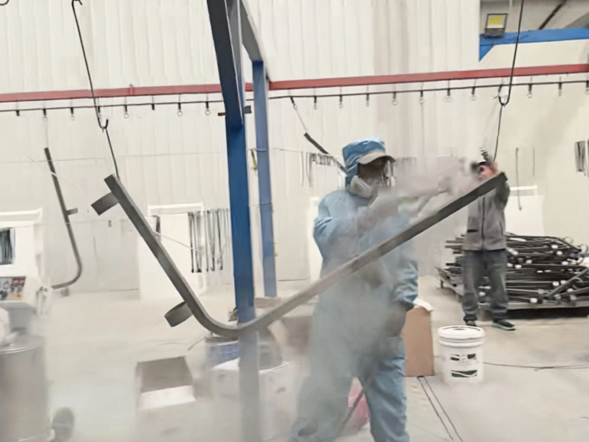
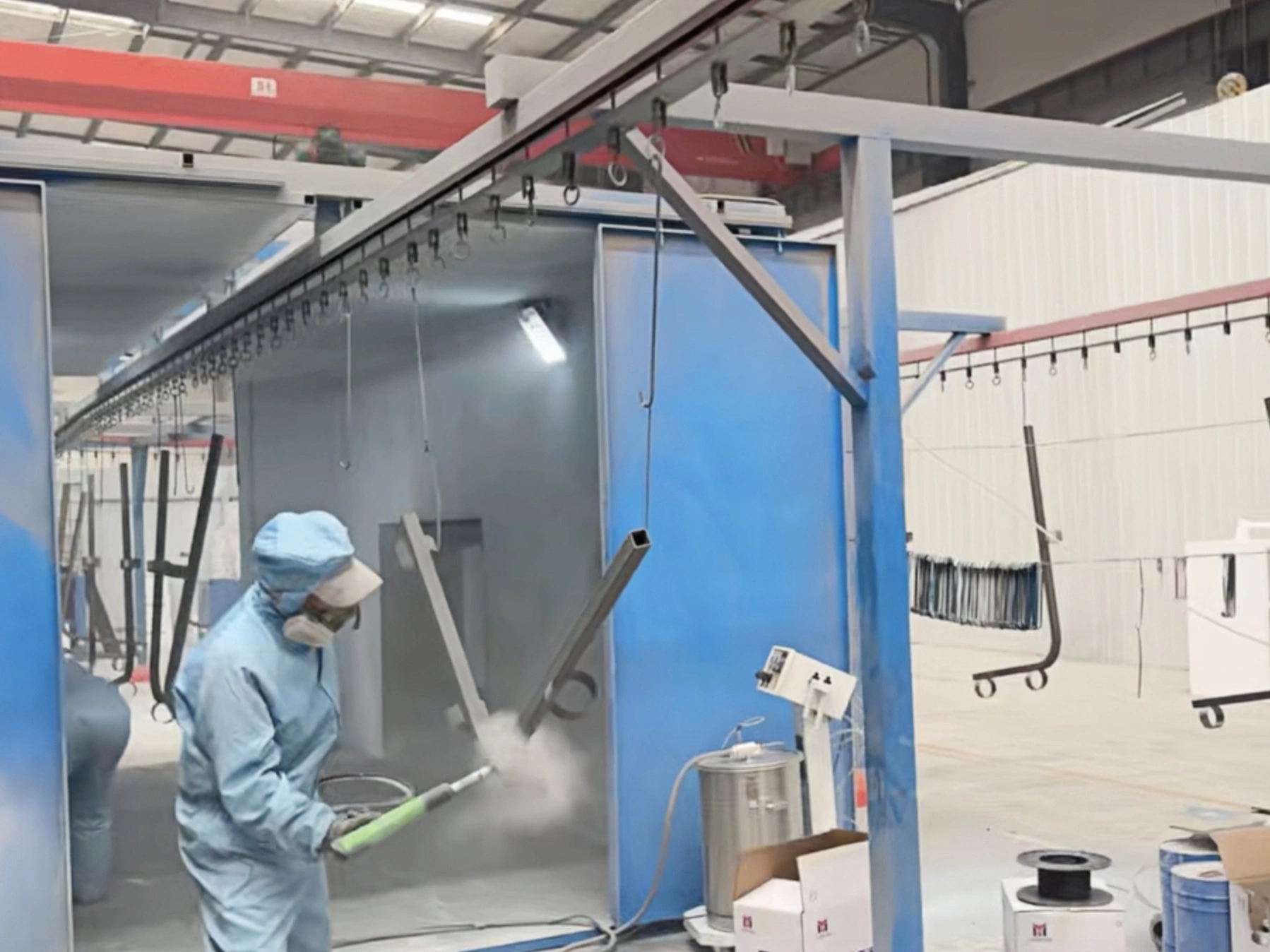
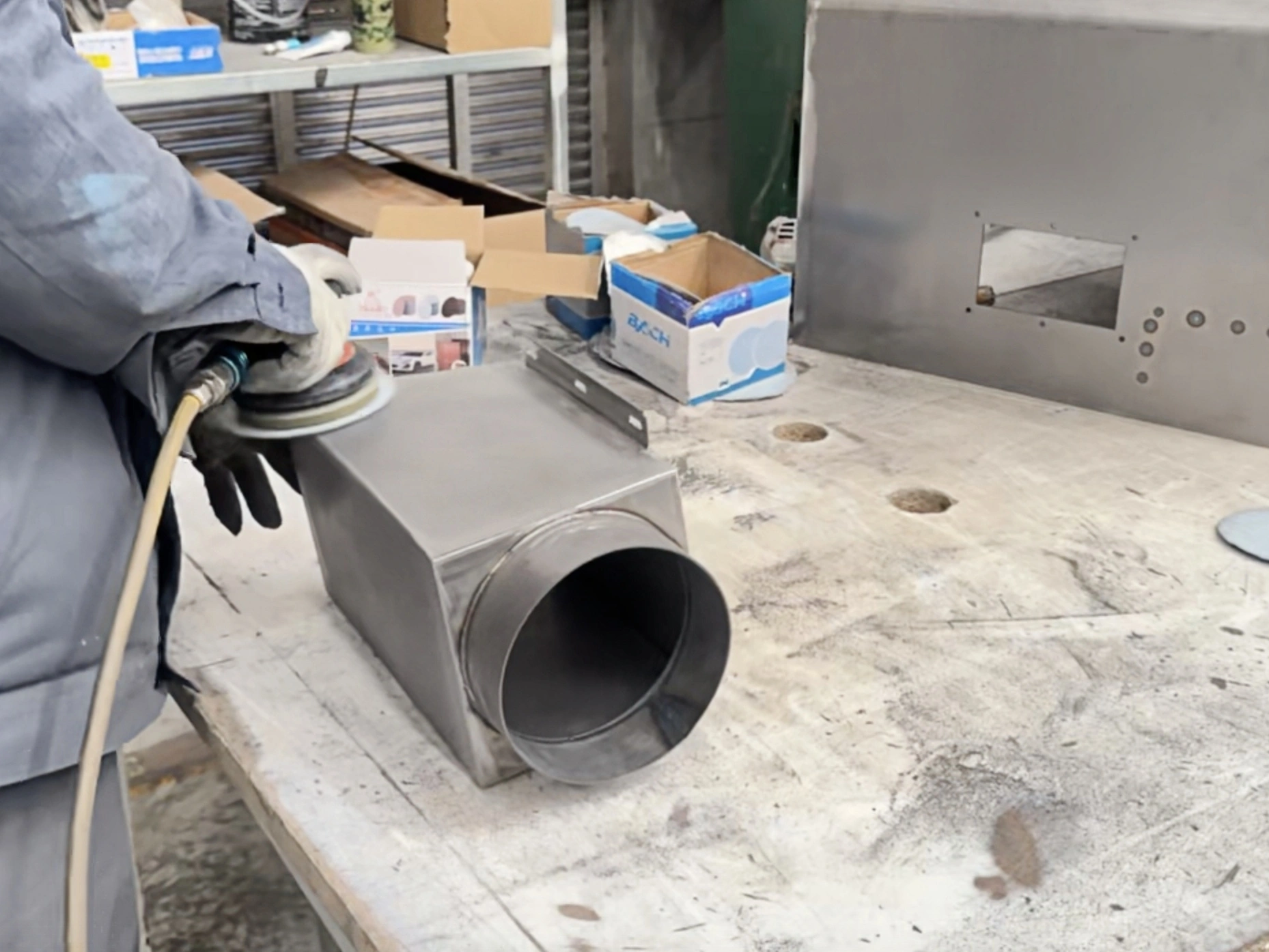
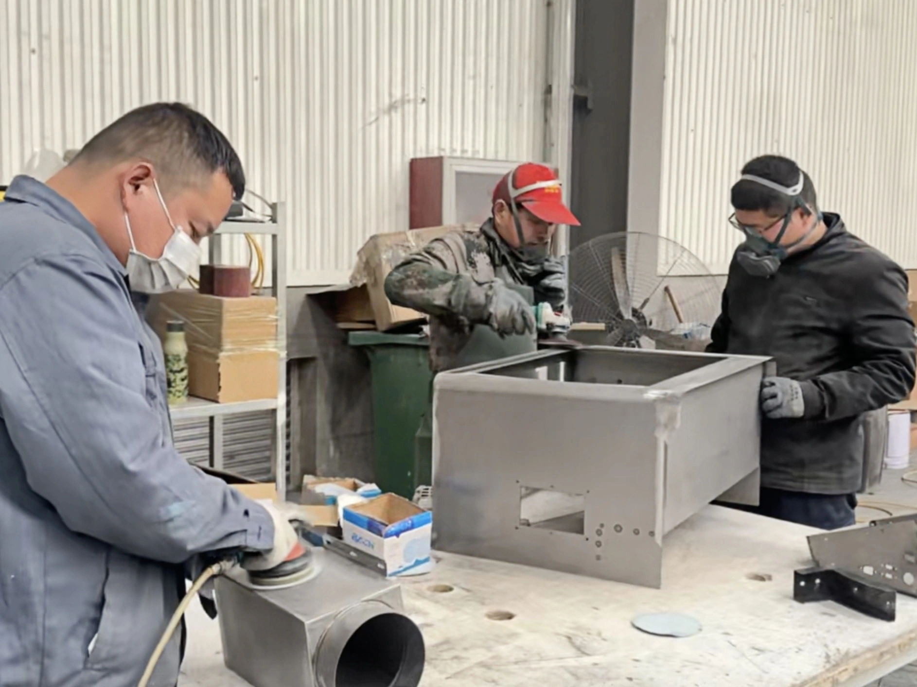
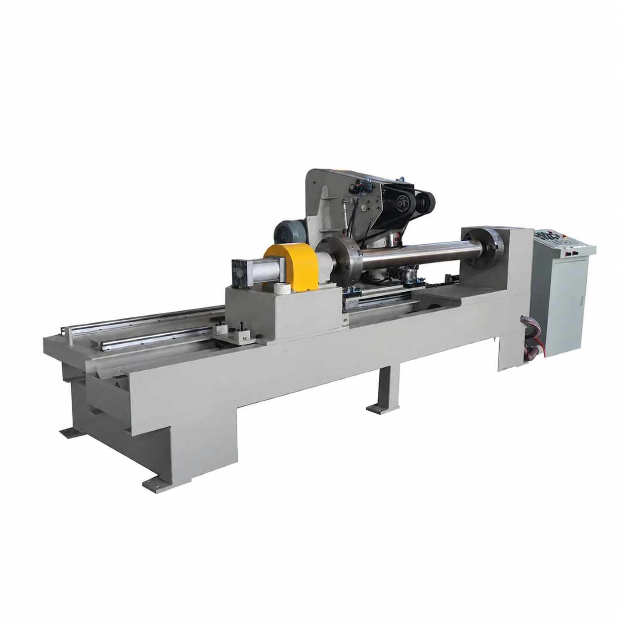
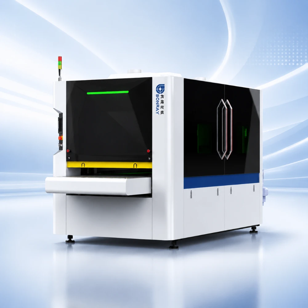
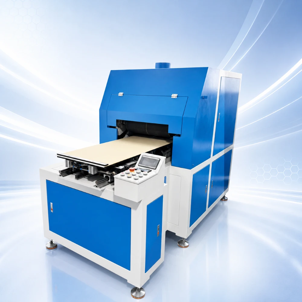
The photographs show a polishing tool aligned with the tube opening, a supported cylindrical workpiece and a workshop arrangement. They help explain access and handling; they are not a measured surface-finish test or a configuration-specific delivery drawing.
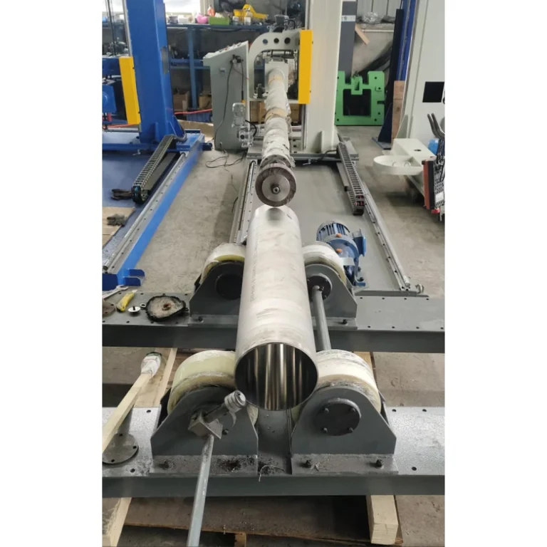
Tool alignment: polishing tool at the open tube end.
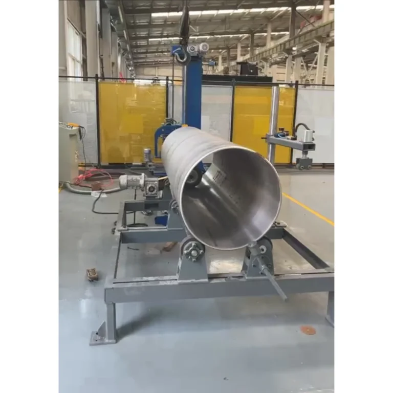
Internal access: the open end shows available polishing-tool access.
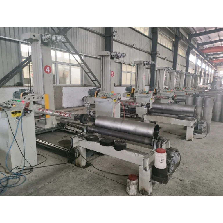
Process setting: machines and cylindrical workpieces in a workshop reference view.
Technical Specifications
| Item | Specification |
|---|---|
| Product name | Internal Tube Polishing Machine |
| Applicable workpiece diameter | Ø350–1000 mm |
| Maximum polishing length per pass | 3,000 mm |
| Overall machine dimensions (L × W × H) | 4,200 × 1,600 × 2,000 mm |
| Machine weight | 2,500 kg |
| Main motor power | 4 kW |
| Roller table | Adjustable, 1 ton |
| Support rollers | 6 × Ø150 mm polyurethane rollers |
| Roller-table drive | 370 W motor + NMRV050 reducer |
| Reducer ratio | 1:80 |
| Motion control | VFD control for beam travel and workpiece rotation |
| Compatible consumables | Replaceable flap wheels and cloth wheels |
Agree on the Internal Surface Result
Specify the material grade, initial scratches or weld condition, permitted stock removal and the surface zones requiring treatment. Wheel type and successive abrasive stages should follow that information, rather than a universal polishing recipe.
For roughness acceptance, state the required Ra, measurement locations and inspection method. For appearance acceptance, use an agreed reference sample. The listed machine power and workpiece range do not establish a mirror finish, a hygiene grade or a fixed cycle time.
A representative trial should include the actual bore geometry and support arrangement. Assess the finish near the entry, mid-length and farthest required position where accessible, and agree on the inspection coverage before production.
Installation, Loading and Delivery Scope
The listed machine envelope is 4,200 x 1,600 x 2,000 mm, with a machine weight of 2,500 kg. Reserve additional space for loading, removal, operator access and maintenance. The 1-ton roller-table rating is separate from the machine weight.
- Dimensioned part drawing with ID, OD, total length, polishing length and end openings.
- Material grade, maximum part weight, wall thickness and available support positions.
- Starting-surface photographs and a finish sample or measurable acceptance requirement.
- Batch quantity, tooling-change needs, loading equipment and workshop access.
- Written delivery scope for wheels, workholding, utilities and any process accessories.
English Product Datasheet
The English datasheet summarises the product-page specifications and the information needed to check workpiece fit. It is not an installation drawing or an operating manual.
Open the English product datasheet (PDF)
Related Surface-Finishing Equipment
For outside tube surfaces, compare the External Round Tube Polishing Machine. For vessel shells and heads, review the Tank & Dished End Polishing Machine; suitability depends on the workpiece and access arrangement.