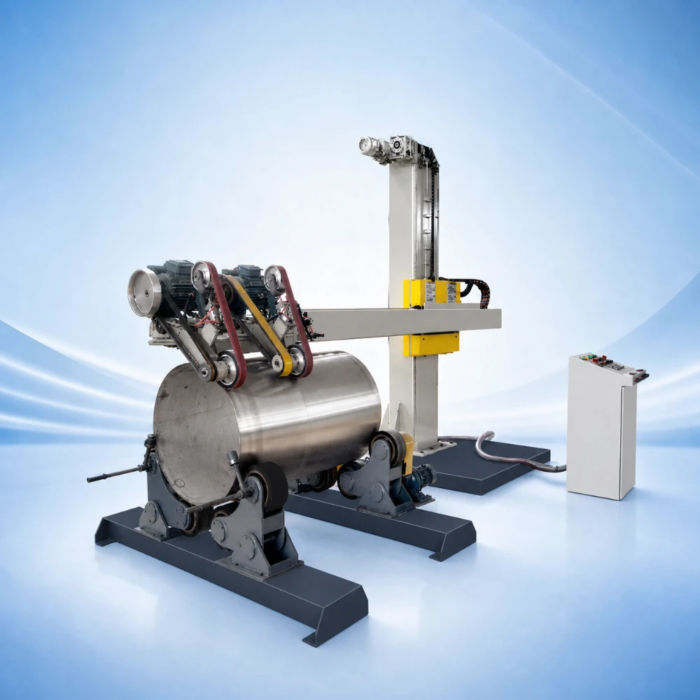
External Polishing for Long, Heavy Pipes
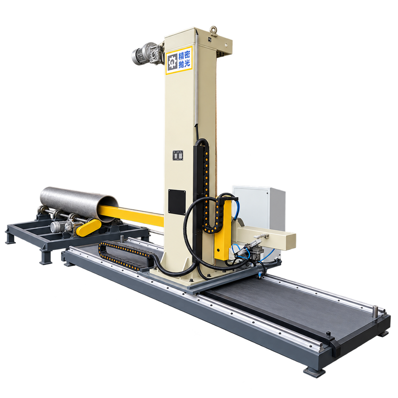
A large-diameter pipe polishing machine for fabricators handling long, heavy stainless-steel and carbon-steel cylindrical workpieces. A travelling abrasive-belt head treats accessible outside surfaces while the chuck and support stands position the pipe for rotation.
The published range is 100-800 mm pipe diameter and 1,000-12,000 mm workpiece length. The polishing head has a 6,000 mm stroke; three support stands provide 8 m total support length. Part length, tool travel and support length are different selection criteria.
Who Uses This Pipe-Finishing Arrangement
- Tube fabricators: external surface preparation and final appearance work before delivery or further assembly.
- Heavy cylindrical-component workshops: processing long pipe sections where stable support, loading access and full-length coverage are central to equipment selection.
- Vessel and heat-exchanger fabricators: finishing compatible cylindrical sections within the published geometry, load and tool-access limits.
This page concerns outside surfaces. It does not describe small-diameter tube processing, internal-bore finishing or a universal machine for every vessel geometry.
Polishing Head, Chuck and Support Arrangement
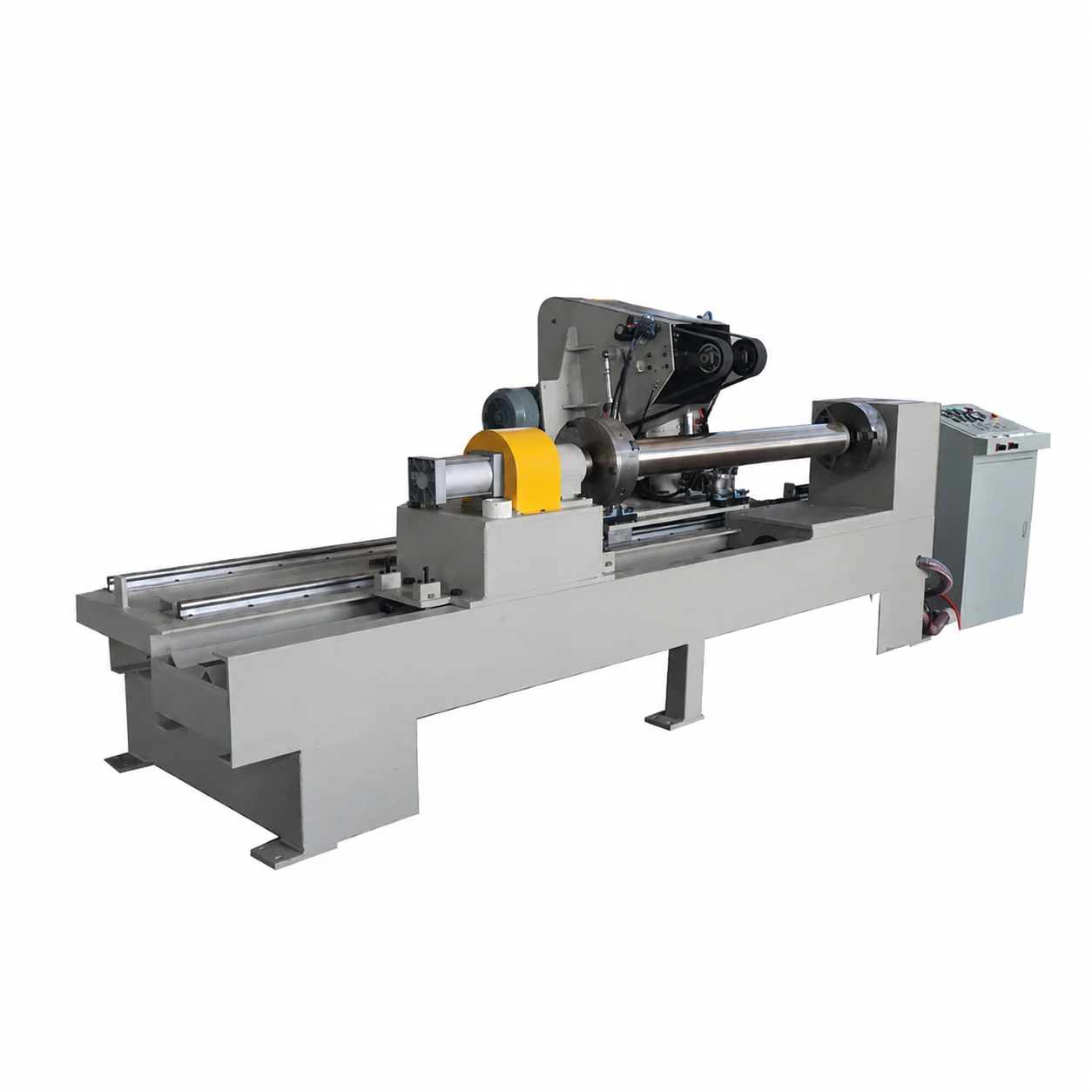
The listed drive system comprises a 7.5 kW inverter-controlled main motor and a 4 kW reducer motor. The adjustable chuck positions the round workpiece, while the support stands carry it during rotation. The longitudinal polishing head uses a 2540 x 50 mm abrasive belt.
The structure photograph is a machine-construction reference, not the complete 12 m installation. The layout drawing below is the appropriate reference for the long-bed arrangement.
Choose the Surface Treatment, Not Just the Belt Grit
- Surface preparation: assess accessible outside marks and initial defects before selecting the material-removal stage.
- Raised weld or burr treatment: specify how much raised material may be removed, the remaining wall requirement and the dimensional allowance. Surface grinding does not repair weld integrity.
- Final polishing: select successive abrasive stages for the approved appearance or roughness. A mirror appearance depends on the starting surface and process; it is not implied by the motor rating.
Keep acceptance criteria tied to the actual material grade and surface condition. Agree on inspection zones and, where needed, a representative sample before assigning a production cycle time.
Technical Specifications
| Item | Specification |
| Pipe Diameter Range | φ100mm – φ800mm |
| Pipe Length Range | 1000mm – 12000mm |
| Max Workpiece Weight | 5 – 10 tons |
| Max Wall Thickness | ≤30mm |
| Applicable Materials | Stainless steel, carbon steel |
| Main Motor Power | 7.5KW, National Standard Motor (inverter) |
| Reducer Motor | 4KW |
| Max Polishing Stroke | 6000mm |
| Support Stand Quantity | 3 (Total Support Length: 8m) |
| Abrasive Belt Size | 2540*50mm |
| Dust Port Diameter | 100mm |
Load Rating and Full-Length Coverage
The maximum-workpiece-weight entry is 5-10 tons. Treat it as configuration-dependent rather than an unconditional 10-ton rating. The published maximum wall thickness is 30 mm; all geometry and load limits must be considered together.
Rotation brings the circumference to the belt; it does not extend the 6,000 mm axial stroke. When the required polishing length is longer, the process agreement must define how each zone is reached, including any repositioning, support changes and overlap between stages.
For a long or heavy pipe, confirm support positions, end projections and loading method before fixing the installation plan. The nominal workpiece-length range is not an installation-footprint dimension or proof of every maximum-size combination.
12 m External-Tube Machine Layout Drawing
The English PDF shows the long-bed machine and its support arrangement in multiple views. It is a layout reference only. The original 12 m drawing and the separate 6 m drawing describe different layouts; neither establishes the complete product-page load, drive or process capacity.
Open the full English machine layout drawing (PDF)
Installation and Dust-Extraction Scope
The listed 100 mm dust port identifies a connection diameter; it does not mean that a collector or ducting is supplied. Extraction must be reviewed for the material, abrasive process and site arrangement.
- Pipe drawing showing OD, total length, required polishing length, wall thickness and end fittings.
- Maximum part weight, intended support positions, loading equipment and workshop access.
- Material grade, incoming-surface photographs and allowed weld or defect removal.
- Approved finish sample or roughness requirement with inspection locations and method.
- Written scope covering machine configuration, consumables, workholding and extraction accessories.
Related Polishing Applications
For bores, review the Internal Tube Polishing Machine. For vessel shells and heads, compare the Tank & Dished End Polishing Machine. For local circumferential weld finishing, see the Circumferential Weld Seam Polishing Machine.