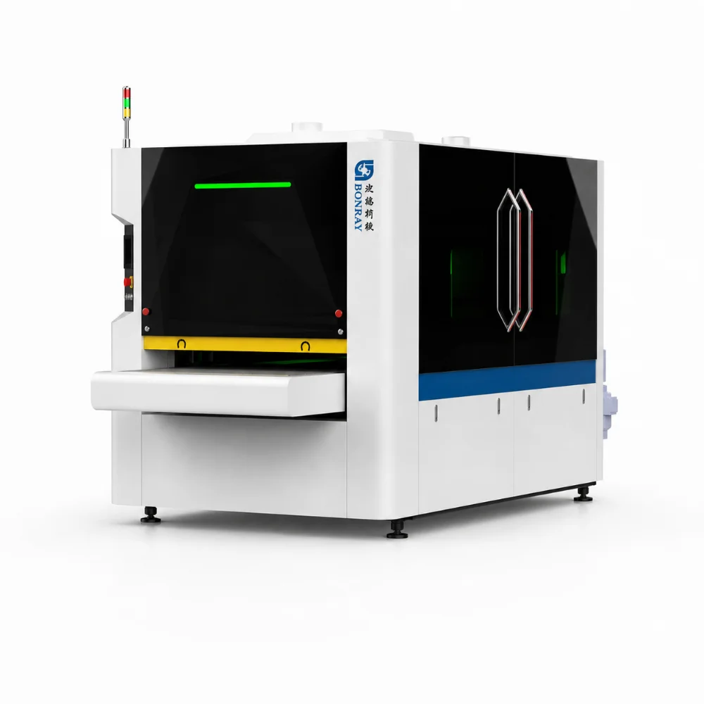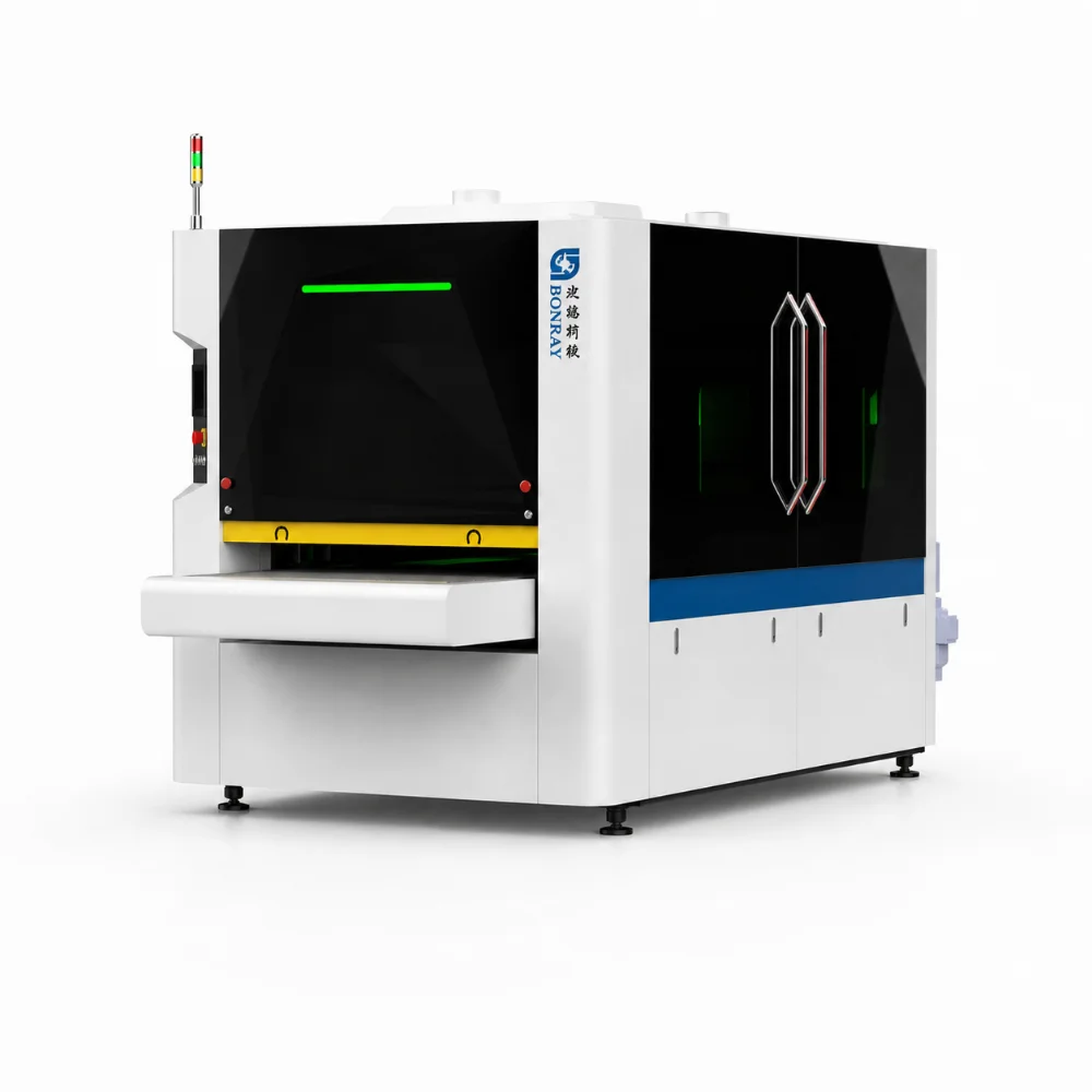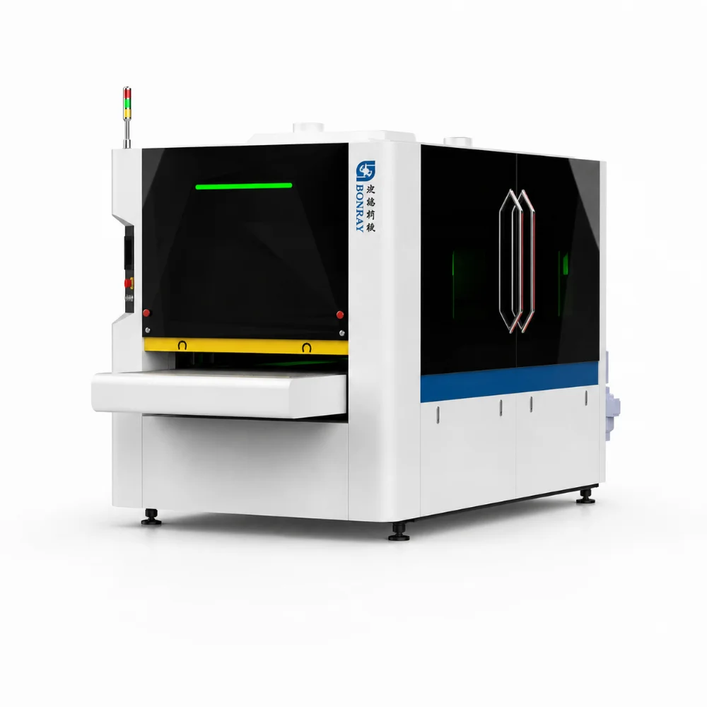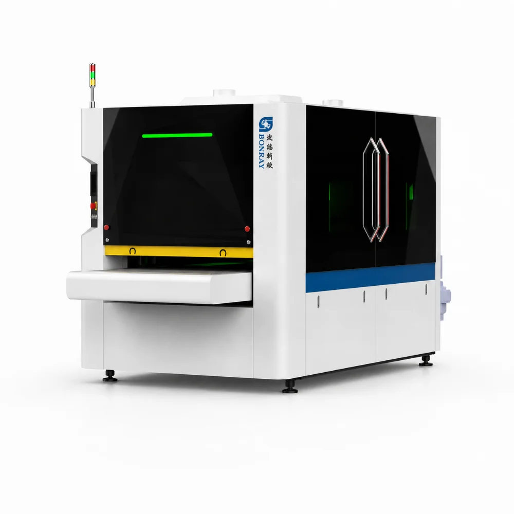
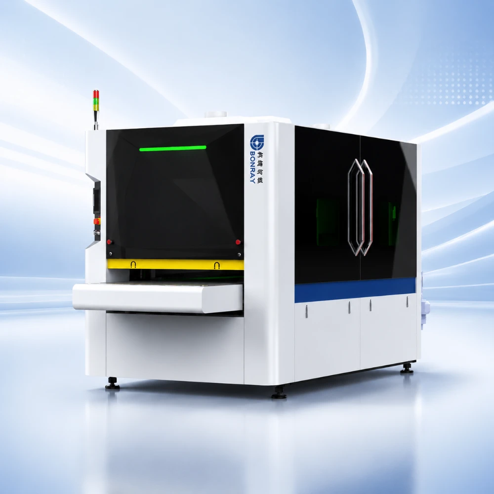
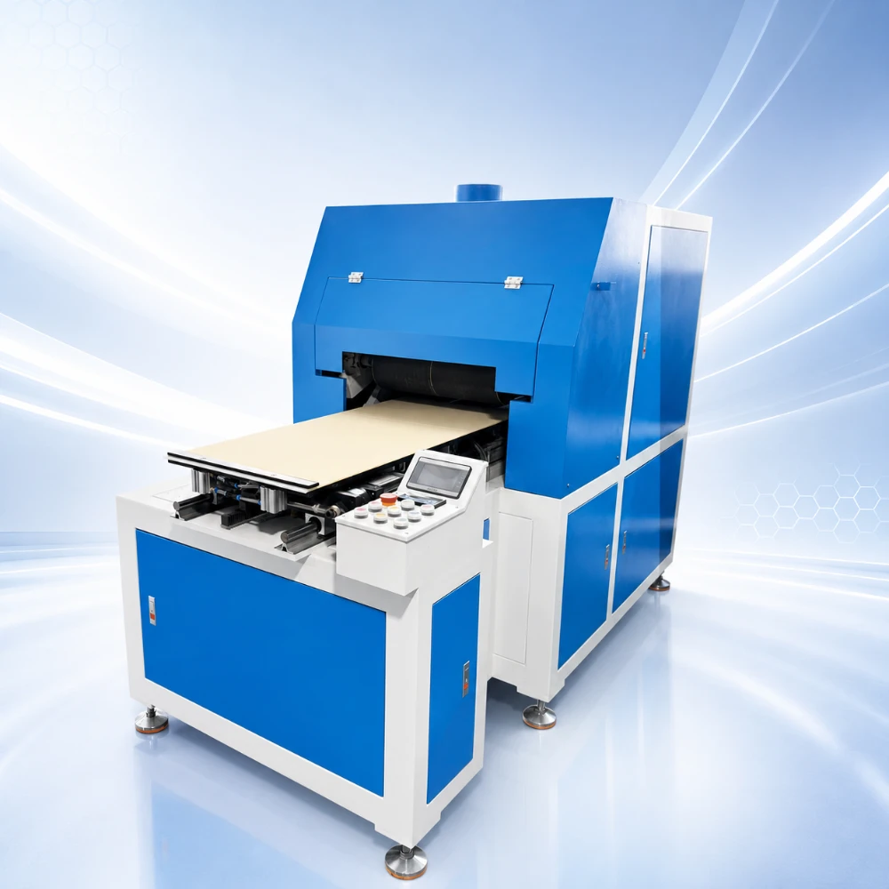
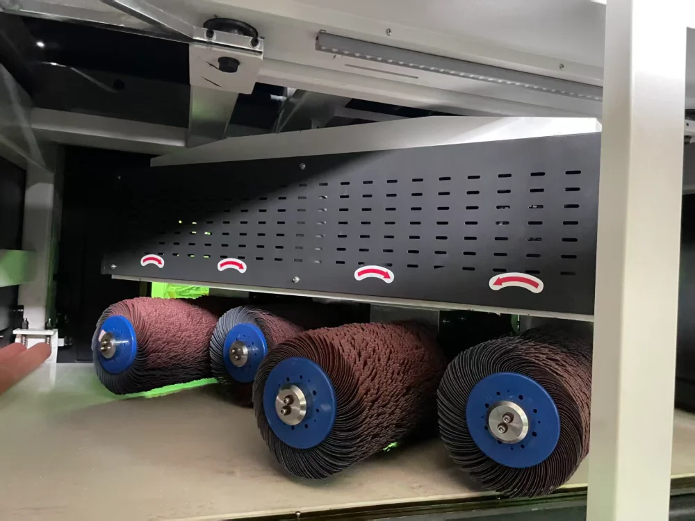
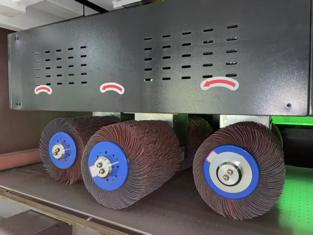
Edge Rounding for Brackets, Panels and Enclosures
A cut sheet metal part can be free of raised burrs and still have a sharp contour. For manufacturers of cabinets, brackets, access panels and fabricated assemblies, the next requirement may be a defined edge break for handling, assembly or coating preparation. Abrasive brush rounding treats the exposed perimeter and accessible internal cutouts while the flat part moves through the machine.
Specify the edge that the finished component needs. An edge break, a measured radius and a machined bevel are different outcomes; the brush setup should be evaluated against the drawing and approved sample.
How the Brush Stage Reaches the Contours
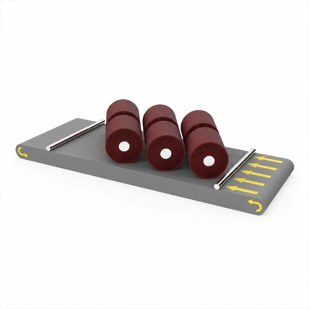
Abrasive brushes rotate on their own axes while a revolving arrangement brings them towards exposed contours from different directions. Brush grade, contact engagement, conveyor speed and pass count influence the result. The tool must be able to enter or reach the feature being treated; an accessible outside edge does not establish coverage of every narrow slot or recessed internal corner.
Choose Rounding Alone or a Combined Sequence
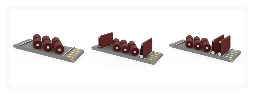
A dedicated R-type brush arrangement suits parts whose primary burrs have already been removed. Its catalogue specification does not include a sanding-belt stage. BBR and BRB arrangements combine belt treatment and brushes when burr removal and contour finishing are both needed. Heavy attached slag may need a separate first stage.
Do not use brush rounding as a way to hide substantial cutting burrs. Establish the incoming burr condition first, then form and inspect the final profile. For thin, small or highly perforated parts, confirm hold-down and conveyor support before setting the brush contact.
Set the Radius and Inspection Requirements
The published application range includes edge radii around 0.5 mm and, for suitable applications, up to 2.0 mm. These remain application-dependent targets, not a guaranteed range on every alloy, thickness or contour. Establish the achievable profile and permitted dimensional change on representative parts before approving the setup.
- Mark the outer contours, holes and slots that require a radius, and identify whether one face or both faces need treatment.
- Define the measurement method, tolerance and permitted dimensional loss, including narrow bridges and small holes.
- Compare the first finished part with the drawing and approved sample; inspect difficult internal features as well as the outer perimeter.
- For coating work, agree the complete cleaning and pretreatment route. A rounded edge alone does not prove coating durability or compliance.
Selection Information
| Selection detail | Information needed |
|---|---|
| Workpiece | Alloy, thickness, smallest and largest dimensions, flatness. |
| Contour | Hole sizes, slots, internal corners and the edges to be treated. |
| Incoming condition | Cutting process, burr height and any oxide or slag. |
| Finished edge | Target radius or edge break, tolerance and inspection method. |
| Production | Batch mix, throughput and whether both faces require treatment. |
Plan Repeat Work and Consumables
Record the selected abrasive brush and validated settings for repeat batches, then inspect the result as brushes wear. A change in material, thickness or incoming cut quality can require a different engagement or pass sequence. Confirm the machine working width and handling limits for the proposed part range; the application page does not define one fixed machine capacity.
Prepare raised burrs with sheet metal deburring, remove heavy cutting residue with slag removal, and specify the visible face separately with surface finishing.